© Antony Anderson 2005
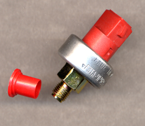
Cruise Brake Pressure Deactivation Switch
showing threaded connection to Brake Master Cylinder and aluminium clamping ring that hold switch and pressure sensing element together.
Pressure Switch Patent
US Patent 4,469, 923 September 4 1984
© Antony Anderson 2005
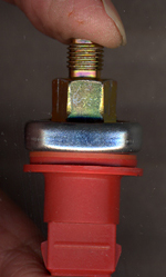
Cruise Brake Pressure Deactivation switch,
(partially disassembled)
(partially disassembled)
Electrical switching Element (Inside red plastic housing)The three parts are held together by an aluminum clamping ring that can be seen in the left hand picture
Elastomeric sealing ring
Pressure sensing element
© Antony Anderson 2005
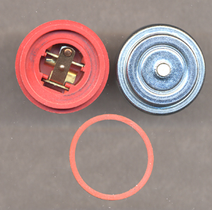
Cruise Brake Pressure Deactivation Switch
(partially disassembled)
Clockwise from top left:
- Electrical switching element (switch is normally held closed by ceramic pin in pressure sensing element
- Pressure sensing element ( with central ceramic pin that acts on switch element: when pressure increases, pin withdraws into pressure sensor housing allowing switch contact to open)
- Elastomeric sealing ring
Note that the pressure
sensor element has a circular fulcrum such that as the pressure
rises the outer annulus of the pressure diaphragm moves
outward and the inner annulus moves inwards so that the ceramic pin,
rather counter-intuitively, moves inwards into the housing allowing the
switch to snap open.
© Antony Anderson 2005
See US Patent 5,932,857 for details of Kapton film used for diaphragm
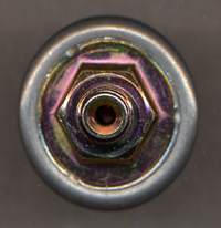
© Antony Anderson 2005
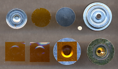
End view of Pressure Sensing Element showing how (5) is spun over edge of (7) to hold the sub-assembly together
Pressure sensing element disassembled
(Counting 11 parts clockwise, from top
left,
1 to 11.)
Parts 1 to 5 assemble as follows: plastic disc(2) fits into (1). Steel convex disc (3) goes on top of (2) and fits into (1). (1-3) fit into underside of housing (5). ceramic pin (4) fits into hole in (5) and rests against convex surface of (4). Other end of pin (4) exerts pressure on switch to close it during normal operation. When pressure rises pin (4) retracts into housing (5) and opens switch.
Part (6) houses elastomer ring (7). Steel annulus (8) has a Kapton square (9) placed upon it as shown. Kapton squares (10) and (11) are placed on (9) to form a three layer diaphragm.
Parts (1-5) are turned over so that raised centre of (1) is facing. Steel annulus (8) is placed on top of parts (1-5) so that raised centre of (1) protrudes through the hole and comes in contact with diaphragm (9). Parts (6) combined with (7) are turned over so that diaphragm (9-11) is clamped between (6+7) and steel annulus (8). Rim of housing (5) is spun over edge of (7) to hold sub-assembly together as a single unit.
