|
|
Investigations |
Innovative Projects |
Example Sites |
Commisssion |
|
& Articles |
|
Contact |
|
|
Dr Antony Anderson C.Eng FIEE |
 |
Helical windings are not new and found limited favour for dynamos in Germany in the late 1880s.[Fritsche] Today they are widely used for small d.c. machines of the ironless type, where they offer the advantage of low inertia and smooth torque at low speeds. They have also been used for linear motors [Eastham & Laithwaite] and transverse flux tubular motors [Eastham & Alwash]. The use in large a.c. machines was first proposed by Ross, Anderson and Macnab of the International Research and Development Company Ltd, who suggested it as a suitable armature for superconducting a.c. generators [UK patent 1975] and this was followed up by a detailed theoretical analysis [Anderson, Bumby and Hassall] published in 1980. A 4 MVA helical armature winding was used by Watnabe et al. as the armature winding for use in either a slotless or a superconducting generator. Conley et al. used a helical winding in an experimental 10 MVA superconducting generator at MIT in the late 1970s. |
|
|
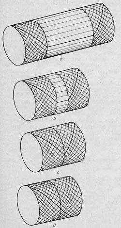
Explanation of the helical windingTo understand how a helical winding works, consider the winding length of a diamond lap winding shown in the adjacent figure (a) to be progressively reduced as (b), by eliminating the so-called central "active" region and allowing the two diamond end windings to coalesce and form a semi-helical winding (c). The true helical winding (d) evolves from the wave wound diamond winding (d).
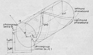
One phase of a two pole helical winding is shown above. Each phase consists of two parallel-connected helical loops, each of which is termed a phase group. Each phase group comprises one right-hand (inner) helical phase band connected in series with a returning left-hand (outer) helical phase band; a right hand phase band being defined as that which traces a right hand screw. |
|